Trestle Design
What's a trestle?
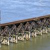
It's a style of bridge where the track runs along the top and is supported by many "bents", a bent being a ladder-like structure.
Here are some pictures of prototype trestles:
And here are a couple of pictures of trestles on other backyard railroads:
Basic Trestle Components
Trestles are composed of two basic parts, the bents and the deck. The deck is a platform for the rails; the bents hold the deck above the ground.
Bents
The deck of a trestle is supported by vertical structures called bents. There are two types of bents:
- The pile bent has round posts which are driven directly into the ground (by a pile driver).
- The frame bent has square posts sitting on a horizontal bottom support member called a mud sill which typically rests on a foundation (concrete, stone, etc).
Both types of bents have a horizontal cap resting on top of the posts which supports the deck. The space between two adjacent bents is called a panel.
Bents have sway braces to prevent lateral swaying.
Deck
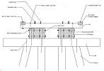
The deck of a trestle starts with a pair of stringers spanning - and resting on the caps of - two adjacent bents. The stringers are spaced so that they are directly below the rails. I bolt a pair of 2"x6" boards together (with a ½" air gap in between) to form each stringer beam (2 beams per panel). I place my bents slightly less than 4 feet apart such that 8' or 12' or 16' lumber can be used.
Bridge ties are then laid on the stringer beams, and 2x2 guard timbers run the length of the deck at the tie ends. In the prototype, the guard timbers were notched to fit over the tie ends and hold them in alignment; I add (glue & nail) blocks to the bottom of the guard timbers because notching is a lot of work. Both ends of each tie is fastened to the guard timbers, and every 10th tie is fastened to the stringers (a technique I observed on the Franklin, NH trestle; I suspect they did this so as to drill a minimum of holes in the stringers).
The running rails (7-1/4" gauge) are attached (with screws) to every tie. Guard rails (which sit inside the running rails and help prevent derailments) are attached to every fourth tie.
Connections

Note: A good deal of the above info was lifted from this page.


